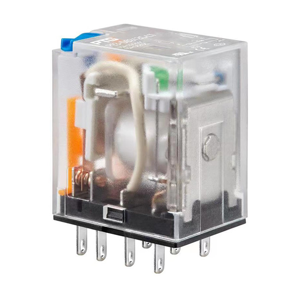
• BackIntermediate Relay
    • PE3Series

    PE3 Series

    Two poles 10 A switching capability, four poles 6 A switching capability
    Products with LED lights, test rods, FWD and other functions optional
    LED light indicates DC/AC coils (GREEN=DC, RED=AC)
    Test rod indicates DC/AC coils (BLUE=DC, RED=AC)
    Gold plated contact optional
    PTG, PTG SPD,PTG relay, PTG防雷器,普泰防雷器,普泰電氣
    • Model Definition
    • Coil Ratings
    • Contact Ratings
    • Characteristics
    • Engineering Data
    • Dimensions
    Series Name
    Terminal Shape Coil Type
    Attached Feature Model
    Coil Voltage
    MPQ
    2 Poles
    10 A
    Embedded terminal DC N/A PE3-□2C 12, 24, 48, 110, 220 10 pcs/tray
    LED light PE3-□2C-L
    LED light and test rod PE3-□2C-LT
    LED light and FWD PE3-□2C-LD
    LED light and gold plated contact PE3-□2C-LA
    4 Poles
    6 A
    N/A PE3-□4C
    LED light PE3-□4C-L
    LED light and test rod PE3-□4C-LT
    LED light and FWD PE3-□4C-LD
    LED light and gold plated contact PE3-□4C-LA
    2 Poles
    10 A
    AC N/A PE3-□2C 24, 48, 115, 230
    LED light PE3-□2C-L
    LED light and test rod PE3-□2C-LT
    LED light and gold plated contact PE3-□2C-LA
    4 poles
    6 A
    N/A PE3-□4C
    LED light PE3-□4C-L
    LED light and test rod PE3-□4C-LT
    LED light and gold plated contact PE3-□4C-LA

    Rated Voltage

    ??(V)

    Rated Current

    ?(mA±10%)

    Coil Resistance?

    (Ω±10%)

    Must Operate Voltage??

    (V)

    Must Release Voltage??

    (V)

    Max. Voltage?

    ?(V)

    Power Consumption

    ?(mW)

    DC 12 66.7 180.0 75% max. of rated voltage 10% max. of rated voltage 110% max. of rated voltage Approx. 900
    DC 24 37.5 640.0
    DC 48 18.5 2,600.0
    DC 110 8.5 13,000.0
    DC 220 5.2 42,000.0
    AC 24 133.3 180.0 80% max. of rated voltage 30% max. of rated voltage Approx. 1200
    AC 48 75.0 640.0
    AC 115 26.0 4,430.0
    AC 230 13.9 16,500.0


    Model 10 A type 6 A type
    Contact Form DPDT(2c) DPDT(4c)
    Contact Type Two poles Four poles
    Contact Material Ag-alloy (Cd free)
    Contact Rating Resistive Load: 250 VAC 10 A
    Resistive Load: 30 VDC 10 A
    Motor Load: 240 VAC 1/3 HP
    Resistive Load: 250 VAC 6 A
    Resistive Load: 30 VDC 6 A
    Motor Load: 240 VAC 1/6 HP
    Max. Switching Voltage 250 VAC/ 30 VDC
    Max. Switching Current 10 A 6 A
    Max. Switching Power AC: 2,500 VA / DC: 300 W AC: 1,500 VA / DC: 180 W
    Min. Switching Power 17 V 10 mA (Products with gold plated contact: 5 V 100 mA or 12 V 10 mA)

    Contact Resistance 50 mΩ max. (at 1 A/ 6 VDC)
    Operate Time ≤20 ms
    Release Time ≤20 ms
    Insulation Resistance ≥1,000 MΩ (500 VDC)
    Dielectric Strength Between Coil and Contacts 2,000 VAC, 1 mA, 50/60 Hz for 1 min
    Between Contacts of TheSame Polarity 1,000 VAC, 1 mA, 50/60 Hz for 1 min
    Between Contacts ofDifferent Polarity 1,500 VAC, 1 mA, 50/60 Hz for 1 min
    Impulse Withstand Voltage Between Coil and Contacts 4 KV (1.2/50 μs)
    Vibration Resistance Destruction 10~55~10 Hz, 0.5 mm single amplitude (1.0 mm double amplitude)
    Malfunction 10~55~10 Hz, 0.5 mm single amplitude (1.0 mm double amplitude)
    Shock Resistance Destruction 980 m/s2 (100 G)
    Malfunction 98 m/s2 (10 G)
    Durability Mechanical 10,000,000 OPS (at 18,000 OPS/hr) 
    Electrical (Res. load) 100,000 OPS (at 1,800 OPS/hr)
    Ambient Temperature -55°C to 70°C(with no icing or condensation)
    Humidity 5~85% RH
    Unit Weight Approx. 35 g


    野花日本HD免费高清版7